
現時点の情報です。最新情報はM5StickC非公式日本語リファレンスを確認してみてください。
概要
ダイソーで300円で販売されている、リモコン付きのイルミネーションライトの赤外線信号を解析してみました。
M5StickCを利用して、解析したリモコン信号を送信するスケッチも作ってみました。
売り場

ダイソーの家電のライトを売っているコーナーで発見しました。とはいっても、なかなか取り扱いがなく、3軒目ぐらいに発見しています。
リモコンが違うバージョンも販売されているようでした。
内容物

リモコンにはボタン電池が最初から入っていて、絶縁用のシートを抜き取ると利用できるようになります。

ライト本体は裏側を回すようにあけると、電池を入れることができます。手元にあった充電式の単3電池をとりあえず入れてみました。

こんな感じで光ります。ライト本体を押すことでスイッチのON、OFFもできますし、リモコンを使って操作もできます。
ただし、リモコンはONで電源をつけてからじゃないと、色が変わりませんでした。
リモコンの解析
IRremoteESP8266というライブラリを利用しました。ライブラリマネージャーより、事前にインストールしておいてください。
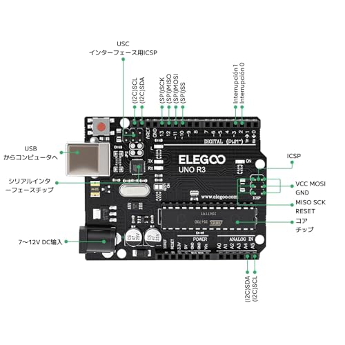
リモコン受信モジュールはM5StickCには搭載されていないので、接続する必要があります。

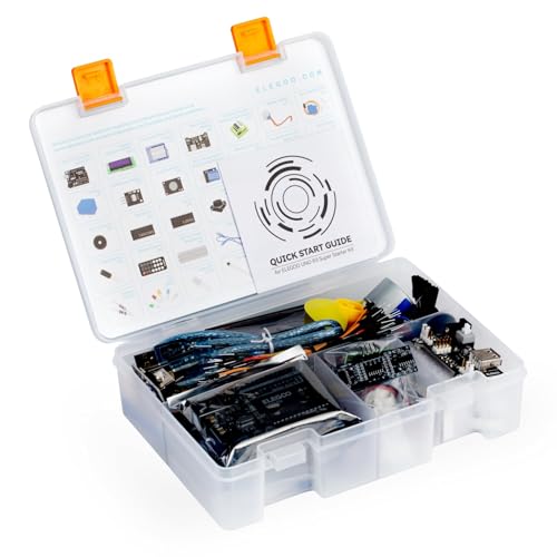
センサーはElegooのセットに入っていた物を利用しました。

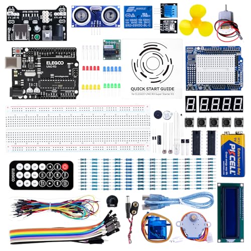


どれを使ってもそう変わらないと思いますが、今であればGrove接続のM5Stack用赤外線送受信ユニットが送料を払っても安いと思います。
センサーのみで基板がついていないやつは、外付けの抵抗などが必要になる可能性があるのでおすすめしません。できればリモコンもついているものの方が、受信確認しやすいですが、今回のライトにもリモコンがあるのでリモコンなしでもいいのかもしれません。
| 赤外線受信 | M5StickC |
| G | GND |
| R | 3.3V |
| Y | GPIO26 |
今回利用した受信モジュールは上記で接続を行いました。Grove接続のM5Stack用赤外線送受信ユニットだと、どこにつなげるのか考えなくてもいいので、楽そうですね。
リモコン受信スケッチ
/*
 * IRremoteESP8266: IRrecvDumpV2 - dump details of IR codes with IRrecv
 * An IR detector/demodulator must be connected to the input kRecvPin.
 *
 * Copyright 2009 Ken Shirriff, http://arcfn.com
 * Copyright 2017-2019 David Conran
 *
 * Example circuit diagram:
 *  https://github.com/crankyoldgit/IRremoteESP8266/wiki#ir-receiving
 *
 * Changes:
 *   Version 1.0 October, 2019
 *     - Internationalisation (i18n) support.
 *     - Stop displaying the legacy raw timing info.
 *   Version 0.5 June, 2019
 *     - Move A/C description to IRac.cpp.
 *   Version 0.4 July, 2018
 *     - Minor improvements and more A/C unit support.
 *   Version 0.3 November, 2017
 *     - Support for A/C decoding for some protocols.
 *   Version 0.2 April, 2017
 *     - Decode from a copy of the data so we can start capturing faster thus
 *       reduce the likelihood of miscaptures.
 * Based on Ken Shirriff's IrsendDemo Version 0.1 July, 2009,
 */
#include <Arduino.h>
#include <IRrecv.h>
#include <IRremoteESP8266.h>
#include <IRac.h>
#include <IRtext.h>
#include <IRutils.h>
// ==================== start of TUNEABLE PARAMETERS ====================
// An IR detector/demodulator is connected to GPIO pin 14
// e.g. D5 on a NodeMCU board.
// Note: GPIO 16 won't work on the ESP8266 as it does not have interrupts.
const uint16_t kRecvPin = 26;
// The Serial connection baud rate.
// i.e. Status message will be sent to the PC at this baud rate.
// Try to avoid slow speeds like 9600, as you will miss messages and
// cause other problems. 115200 (or faster) is recommended.
// NOTE: Make sure you set your Serial Monitor to the same speed.
const uint32_t kBaudRate = 115200;
// As this program is a special purpose capture/decoder, let us use a larger
// than normal buffer so we can handle Air Conditioner remote codes.
const uint16_t kCaptureBufferSize = 1024;
// kTimeout is the Nr. of milli-Seconds of no-more-data before we consider a
// message ended.
// This parameter is an interesting trade-off. The longer the timeout, the more
// complex a message it can capture. e.g. Some device protocols will send
// multiple message packets in quick succession, like Air Conditioner remotes.
// Air Coniditioner protocols often have a considerable gap (20-40+ms) between
// packets.
// The downside of a large timeout value is a lot of less complex protocols
// send multiple messages when the remote's button is held down. The gap between
// them is often also around 20+ms. This can result in the raw data be 2-3+
// times larger than needed as it has captured 2-3+ messages in a single
// capture. Setting a low timeout value can resolve this.
// So, choosing the best kTimeout value for your use particular case is
// quite nuanced. Good luck and happy hunting.
// NOTE: Don't exceed kMaxTimeoutMs. Typically 130ms.
#if DECODE_AC
// Some A/C units have gaps in their protocols of ~40ms. e.g. Kelvinator
// A value this large may swallow repeats of some protocols
const uint8_t kTimeout = 50;
#else   // DECODE_AC
// Suits most messages, while not swallowing many repeats.
const uint8_t kTimeout = 15;
#endif  // DECODE_AC
// Alternatives:
// const uint8_t kTimeout = 90;
// Suits messages with big gaps like XMP-1 & some aircon units, but can
// accidentally swallow repeated messages in the rawData[] output.
//
// const uint8_t kTimeout = kMaxTimeoutMs;
// This will set it to our currently allowed maximum.
// Values this high are problematic because it is roughly the typical boundary
// where most messages repeat.
// e.g. It will stop decoding a message and start sending it to serial at
//      precisely the time when the next message is likely to be transmitted,
//      and may miss it.
// Set the smallest sized "UNKNOWN" message packets we actually care about.
// This value helps reduce the false-positive detection rate of IR background
// noise as real messages. The chances of background IR noise getting detected
// as a message increases with the length of the kTimeout value. (See above)
// The downside of setting this message too large is you can miss some valid
// short messages for protocols that this library doesn't yet decode.
//
// Set higher if you get lots of random short UNKNOWN messages when nothing
// should be sending a message.
// Set lower if you are sure your setup is working, but it doesn't see messages
// from your device. (e.g. Other IR remotes work.)
// NOTE: Set this value very high to effectively turn off UNKNOWN detection.
const uint16_t kMinUnknownSize = 12;
// Legacy (No longer supported!)
//
// Change to `true` if you miss/need the old "Raw Timing[]" display.
#define LEGACY_TIMING_INFO false
// ==================== end of TUNEABLE PARAMETERS ====================
// Use turn on the save buffer feature for more complete capture coverage.
IRrecv irrecv(kRecvPin, kCaptureBufferSize, kTimeout, true);
decode_results results;  // Somewhere to store the results
// This section of code runs only once at start-up.
void setup() {
#if defined(ESP8266)
  Serial.begin(kBaudRate, SERIAL_8N1, SERIAL_TX_ONLY);
#else  // ESP8266
  Serial.begin(kBaudRate, SERIAL_8N1);
#endif  // ESP8266
  while (!Serial)  // Wait for the serial connection to be establised.
    delay(50);
  Serial.printf("\n" D_STR_IRRECVDUMP_STARTUP "\n", kRecvPin);
#if DECODE_HASH
  // Ignore messages with less than minimum on or off pulses.
  irrecv.setUnknownThreshold(kMinUnknownSize);
#endif  // DECODE_HASH
  irrecv.enableIRIn();  // Start the receiver
}
// The repeating section of the code
void loop() {
  // Check if the IR code has been received.
  if (irrecv.decode(&results)) {
    // Display a crude timestamp.
    uint32_t now = millis();
    Serial.printf(D_STR_TIMESTAMP " : %06u.%03u\n", now / 1000, now % 1000);
    // Check if we got an IR message that was to big for our capture buffer.
    if (results.overflow)
      Serial.printf(D_WARN_BUFFERFULL "\n", kCaptureBufferSize);
    // Display the library version the message was captured with.
    Serial.println(D_STR_LIBRARY "   : v" _IRREMOTEESP8266_VERSION_ "\n");
    // Display the basic output of what we found.
    Serial.print(resultToHumanReadableBasic(&results));
    // Display any extra A/C info if we have it.
    String description = IRAcUtils::resultAcToString(&results);
    if (description.length()) Serial.println(D_STR_MESGDESC ": " + description);
    yield();  // Feed the WDT as the text output can take a while to print.
#if LEGACY_TIMING_INFO
    // Output legacy RAW timing info of the result.
    Serial.println(resultToTimingInfo(&results));
    yield();  // Feed the WDT (again)
#endif  // LEGACY_TIMING_INFO
    // Output the results as source code
    Serial.println(resultToSourceCode(&results));
    Serial.println();    // Blank line between entries
    yield();             // Feed the WDT (again)
  }
}
IRremoteESP8266のスケッチ例にあるIRrecvDumpV2を利用しました。GPIOだけ14から26に変更しています。
Grove接続のM5Stack用赤外線送受信ユニットだとGPIO33が受信かな?
受信結果
Protocol  : NEC
Code      : 0x1FE48B7 (32 Bits)
uint16_t rawData[67] = {9144, 4478,  614, 522,  616, 526,  610, 522,  614, 522,  614, 522,  616, 522,  616, 522,  616, 1654,  590, 1654,  592, 1654,  590, 1654,  590, 1634,  610, 1632,  612, 1654,  590, 1656,  588, 522,  616, 522,  614, 1654,  590, 524,  614, 522,  612, 1656,  590, 524,  614, 520,  616, 522,  614, 1632,  612, 522,  616, 1654,  590, 1654,  590, 522,  614, 1654,  590, 1654,  590, 1654,  588};  // NEC 1FE48B7
uint32_t address = 0x80;
uint32_t command = 0x12;
uint64_t data = 0x1FE48B7;
上記のようなコードが受信できます。Protocolは標準的なNECですね。Codeの0x1FE48B7が受信したデータそのもので、それを分析するとaddressとcommandがわかります。
リモコンの配置
| POWER ON | POWER OFF | MODE |
| 4H | 8H | Multi Color |
| Red | Green | Blue |
| Orange | Lime | Navy |
| Yellow | Aqua | Pink |
| White | Skyblue | Purple |
横3個、縦6個の全部で18個のボタンがあります。色名はわたしがつけたものですので、間違っている可能性があります。リモコンの見た目と、実際のライトの色が違うのでちょっと名前付けが難しかったです。
コマンド
| 0x12 | 0x1A | 0x1E |
| 0x01 | 0x02 | 0x03 |
| 0x04 | 0x05 | 0x06 |
| 0x07 | 0x08 | 0x09 |
| 0x0A | 0x1B | 0x1F |
| 0x0C | 0x0D | 0x0E |
addressはすべて0x80でしたので、commandだけ表にしました。番号が不自然に飛んでいますので、別の用途のリモコンを流用しているのかもしれません。
コード
| 0x1FE48B7 | 0x1FE58A7 | 0x1FE7887 |
| 0x1FE807F | 0x1FE40BF | 0x1FEC03F |
| 0x1FE20DF | 0x1FEA05F | 0x1FE609F |
| 0x1FEE01F | 0x1FE10EF | 0x1FE906F |
| 0x1FE50AF | 0x1FED827 | 0x1FEF807 |
| 0x1FE30CF | 0x1FEB04F | 0x1FE708F |
生データであるコードものせておきます。
リモコンの赤外線送信
#include <M5StickC.h>
#include <IRremoteESP8266.h>
#include <IRsend.h>
#include <IRutils.h>

const uint16_t kIrLed = 9;              // M5StickCはGPIO9にIRが内蔵

IRsend irsend(kIrLed);                  // IR送信を宣言

const uint32_t IR_ADDRESS = 0x0080;     // アドレス

// リモコンコード保存用構造体
struct REMOTE {
  char name[16];
  uint8_t command;
};

// リモコンコード一覧
REMOTE remote[] = {
  { "POWER ON"    , 0x12 },
  { "POWER OFF"   , 0x1A },
  { "MODE"        , 0x1E },
  { "4H"          , 0x01 },
  { "8H"          , 0x02 },
  { "Multi Color" , 0x03 },
  { "Red"         , 0x04 },
  { "Green"       , 0x05 },
  { "Blue"        , 0x06 },
  { "Orange"      , 0x07 },
  { "Lime"        , 0x08 },
  { "Navy"        , 0x09 },
  { "Yellow"      , 0x0A },
  { "Aqua"        , 0x1B },
  { "Pink"        , 0x1F },
  { "White"       , 0x0C },
  { "Skyblue"     , 0x0D },
  { "Purple"      , 0x0E },
};

int cursor = 0; // カーソル位置

void setup() {
  M5.begin();     // M5StickC初期化
  irsend.begin(); // IR初期化

  // リモコン項目表示
  M5.Lcd.fillScreen(BLACK);
  M5.Lcd.setCursor(0, 8);
  for ( int i = 0 ; i < ( sizeof(remote) / sizeof(REMOTE) ) ; i++ ) {
    M5.Lcd.print((cursor == i) ? ">" : " ");
    M5.Lcd.println(remote[i].name);
  }
}

void loop() {
  M5.update();  // ボタン状態更新

  // M5ボタンで送信
  if ( M5.BtnA.wasPressed() ) {
    // 送信データ作成
    uint64_t send = irsend.encodeNEC(IR_ADDRESS, remote[cursor].command);
    // 送信
    irsend.sendNEC(send);

    // デバッグ表示
    Serial.printf("Send IR : 0x%08LX", send);
    Serial.printf("(address=0x%04X, ", IR_ADDRESS);
    Serial.printf("command=0x%02X)\n", remote[cursor].command);
  }

  // 右ボタンでカーソル移動
  if ( M5.BtnB.wasPressed() ) {
    cursor++;
    cursor = cursor % ( sizeof(remote) / sizeof(REMOTE) );

    // カーソル描画
    M5.Lcd.setCursor(0, 8);
    for ( int i = 0 ; i < ( sizeof(remote) / sizeof(REMOTE) ) ; i++ ) {
      M5.Lcd.println((cursor == i) ? ">" : " ");
    }
  }

  delay(100);
}
M5StickCでの送信例です。信号解析で利用した受信ユニットは必要ないので取り外します。
IR送信はGPIO9に接続されているので、内蔵の赤外線送信ユニットを使います。ただし、内蔵の赤外線送信ユニットは若干出力が弱いので、あまり遠くまで飛びません。
Grove接続のM5Stack用赤外線送受信ユニットを使って、GPIO32から送信したほうが、より遠距離まで信号は届くと思います。
    // 送信データ作成
    uint64_t send = irsend.encodeNEC(IR_ADDRESS, remote[cursor].command);
    // 送信
    irsend.sendNEC(send);
肝になるのが、上記の処理です。NECプロトコルだったのでNECとついている関数を利用します。encodeNEC()関数でアドレスとコマンドから、実際に送信するCodeを作成し、sendNEC()関数で送信します。
あとは描画やカーソル処理などになるので、たいした処理はやっていません。
コード指定
#include <M5StickC.h>
#include <IRremoteESP8266.h>
#include <IRsend.h>
#include <IRutils.h>
const uint16_t kIrLed = 9;              // M5StickCはGPIO9にIRが内蔵
IRsend irsend(kIrLed);                  // IR送信を宣言
// リモコンコード保存用構造体
struct REMOTE {
  char name[16];
  uint64_t code;
};
// リモコンコード一覧
REMOTE remote[] = {
  { "POWER ON"    , 0x1FE48B7 },
  { "POWER OFF"   , 0x1FE58A7 },
  { "MODE"        , 0x1FE7887 },
  { "4H"          , 0x1FE807F },
  { "8H"          , 0x1FE40BF },
  { "Multi Color" , 0x1FEC03F },
  { "Red"         , 0x1FE20DF },
  { "Green"       , 0x1FEA05F },
  { "Blue"        , 0x1FE609F },
  { "Orange"      , 0x1FEE01F },
  { "Lime"        , 0x1FE10EF },
  { "Navy"        , 0x1FE906F },
  { "Yellow"      , 0x1FE50AF },
  { "Aqua"        , 0x1FED827 },
  { "Pink"        , 0x1FEF807 },
  { "White"       , 0x1FE30CF },
  { "Skyblue"     , 0x1FEB04F },
  { "Purple"      , 0x1FE708F },
};
int cursor = 0; // カーソル位置
void setup() {
  M5.begin();     // M5StickC初期化
  irsend.begin(); // IR初期化
  // リモコン項目表示
  M5.Lcd.fillScreen(BLACK);
  M5.Lcd.setCursor(0, 8);
  for ( int i = 0 ; i < ( sizeof(remote) / sizeof(REMOTE) ) ; i++ ) {
    M5.Lcd.print((cursor == i) ? ">" : " ");
    M5.Lcd.println(remote[i].name);
  }
}
void loop() {
  M5.update();  // ボタン状態更新
  // M5ボタンで送信
  if ( M5.BtnA.wasPressed() ) {
    // 送信
    irsend.sendNEC(remote[cursor].code);
    // デバッグ表示
    Serial.printf("Send IR : 0x%08LX", remote[cursor].code);
  }
  // 右ボタンでカーソル移動
  if ( M5.BtnB.wasPressed() ) {
    cursor++;
    cursor = cursor % ( sizeof(remote) / sizeof(REMOTE) );
    // カーソル描画
    M5.Lcd.setCursor(0, 8);
    for ( int i = 0 ; i < ( sizeof(remote) / sizeof(REMOTE) ) ; i++ ) {
      M5.Lcd.println((cursor == i) ? ">" : " ");
    }
  }
  delay(100);
}
ほぼ変わっていませんが、チャンネルとコマンドの変わりにコードをそのまま使っている場合です。
    // 送信
    irsend.sendNEC(remote[cursor].code);
エンコードしなくてもよいので、送信はスッキリしています。コードを使うのかコマンドを使うのかは好みなので、どちらを利用しても構いません。
学習リモコン的な使い方の場合にはコードをそのまま使ったほうが楽だと思いますし、手で確認しているときにはコマンドがわかったほうが、目視で確認しやすいです。
分解

ネジ4本で止まっているだけなので、かんたんに分解することができます。

右下に赤外線受信ユニットがあって、左側に電源スイッチがありますね。さて、ここに赤外線受信ユニットがあるってことは、、、
赤外線ユニットに上にある3つのハンダからパターンを追っていくと、左が電源で真ん中がGND、右が信号みたいです。とりあえずGNDとGND、信号とGPIO26を接続して、リモコン信号を受信すると、、、なんと受信できました。
とはいえ、おすすめしない方法なのでマネはしないでください。電源が1.2Vのエネループが3本なので3.6Vとちょっと高めの信号が入ってきます。新品のアルカリ電池とかだと1.7Vが3本で5.1VなのでESP32が壊れる可能性があります。
そもそも、分解しないでください!
まとめ
いまは300円でもこんなものがあるんですね。中国だとリモコンと受信ユニットのセットで100円以下で買えるので、たしかにもろもろで300円にはなるのかもしれません。

コメント